


So, what exactly is transformer winding? In simple terms, transformer windings are carefully arranged coils of wire—typically copper or aluminum—wound around a magnetic core to transfer electrical energy within a transformer. When alternating current (AC) passes through the primary winding, it produces a changing magnetic field that induces voltage in the secondary winding. This principle, known as electromagnetic induction, allows a transformer to increase or reduce voltage efficiently to suit different electrical applications.
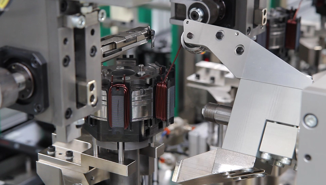
Whether supplying power to a home appliance or supporting equipment across an entire factory, high-quality transformer windings are essential for reliable and efficient voltage conversion. Produced with precise winding machines, each transformer winding helps ensure the required voltage is delivered safely while supporting the efficient transfer of electrical energy within the power system.
Primary & Secondary Transformer Windings: Working Principle
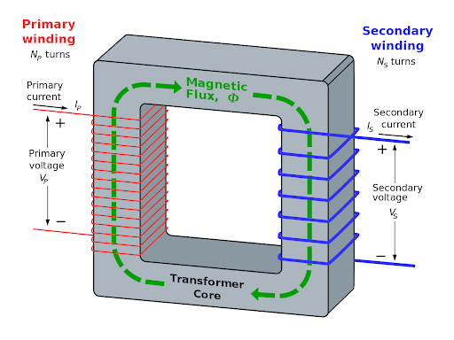
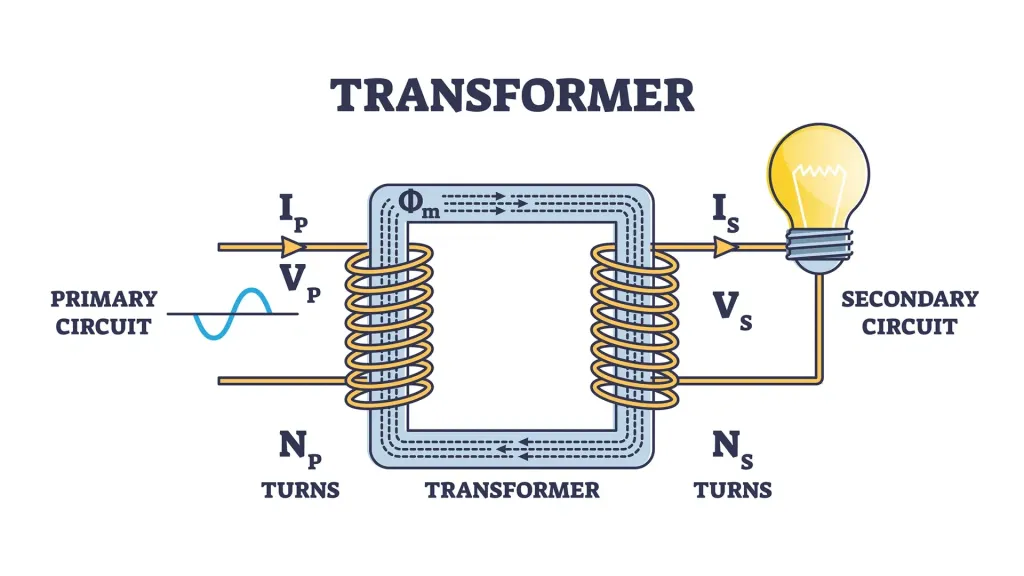
A typical transformer consists of two main sets of transformer windings: the primary winding and the secondary winding.
The primary winding is connected directly to the input power source. When AC current flows through it, it generates a changing magnetic field within the transformer core. This magnetic field is essential to the transformer winding process, allowing electrical energy to be transferred from the primary side to the secondary side.
The secondary winding is positioned close to the primary winding, where it responds to the changing magnetic field. Through electromagnetic induction, a new voltage is induced in the secondary winding and delivered to the output load, such as appliances, tools, or industrial equipment.
The number of turns in the primary and secondary transformer windings determines whether the voltage is increased (step-up) or reduced (step-down). This simple but effective transformer winding principle enables transformers to provide the appropriate voltage for different electrical applications.
How Transformer Windings Work
To understand how transformer windings work, it helps to start with a fundamental principle of physics—Faraday’s Law of Electromagnetic Induction. When the electric current flowing through the primary winding changes, it produces a changing magnetic field within the transformer core. This magnetic field then induces a voltage in the secondary winding, allowing electrical energy to be transferred between the transformer windings.
The voltage produced in the secondary winding depends on the number of turns in the primary and secondary transformer windings. This relationship is known as the turns ratio.
For example, if the primary winding has 100 turns and the secondary has 50, the output voltage is reduced by half, creating a step-down transformer. If the secondary winding has more turns than the primary, the transformer instead steps the voltage up.
A simple rule helps explain how transformer windings work:
- Voltage ratio = Turns ratio
- Current ratio = Inverse of the turns ratio
This is one of the key advantages of transformer winding: voltage levels can be increased or reduced efficiently without moving parts, relying on electromagnetic principles and the relationship between winding turns.
Transformer Winding and Core Layouts
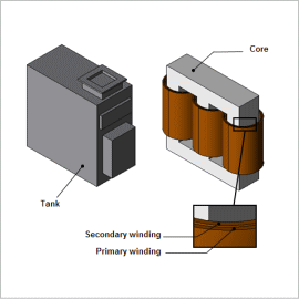
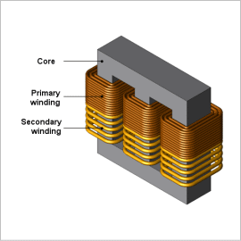
The arrangement of transformer windings around the core has a direct impact on transformer efficiency and performance. In many designs, the windings are placed around a laminated iron core, which helps reduce eddy currents—circulating electrical currents that can generate unwanted heat and energy loss. By limiting these losses, the laminated core helps maintain efficient and concentrated magnetic flux during transformer winding operation.
There are two common layouts for transformer windings: core-type and shell-type. In a core-type transformer, the windings are arranged around the core, while in a shell-type transformer, the core surrounds the windings. The choice of layout influences how effectively magnetic flux is transferred between the coils and how much leakage flux—magnetic flux that does not link both windings—is produced.
The most suitable transformer winding layout depends on factors such as transformer size, voltage level, and cooling requirements. Both designs, however, are intended to improve magnetic coupling and use the magnetic energy generated by the windings efficiently.
Common Transformer Winding Types
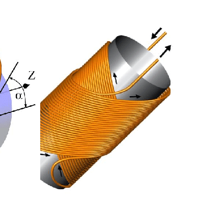
Transformer windings can be arranged in different patterns to suit specific applications, space limitations, voltage levels, and cooling requirements. Common transformer winding types include:
Helical Winding: A spiral-shaped winding commonly used in high-current transformers. Its simple and robust structure makes it well suited for handling large currents.
Disc Winding: Built from flat coil sections arranged in layers, this design provides effective cooling and is commonly used in medium- to high-voltage transformers.
Sandwich Winding: Primary and secondary winding sections are arranged alternately to reduce leakage flux and improve magnetic coupling between the transformer windings.
Toroidal Winding: The coil is wound around a ring-shaped toroidal core, creating a compact and efficient design with low electromagnetic interference.
Each transformer winding type offers specific advantages. Some designs provide a more compact structure, while others improve heat dissipation or help reduce energy losses. Choosing the right transformer winding depends on the transformer’s application, operating conditions, and performance requirements.
Transformer Winding Materials & Losses
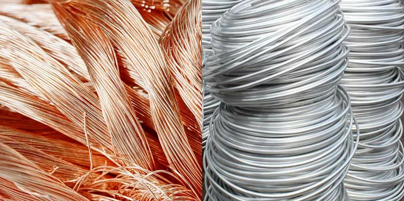
Transformer windings are commonly made from copper or aluminum, with each material offering different advantages. Copper is widely preferred for transformer winding because of its excellent electrical conductivity, strength, and ability to support a more compact winding design while handling higher electrical loads. Aluminum, by comparison, is lighter and more affordable, making it a practical option when reducing weight or overall cost is a priority.
However, no transformer winding material is completely free from energy loss. As current flows through the transformer windings, electrical resistance causes some energy to be converted into heat. This is known as copper loss, or I²R loss, and occurs because of the resistance of the winding conductor. Another source of loss is leakage flux, where part of the magnetic flux escapes instead of effectively linking the primary and secondary windings.
These energy losses, including copper loss and leakage flux, can reduce a transformer’s overall efficiency. For this reason, proper transformer winding design and careful selection of winding materials are essential for minimizing energy losses and achieving reliable, efficient transformer performance.
Conclusion
Transformer winding is at the core of transformer operation, enabling safe and efficient voltage conversion through carefully designed copper or aluminum coils. Understanding different transformer winding types, layouts, and materials can help you select or design a transformer that better matches your application and performance requirements.
If you have questions or need support choosing the right winding solution, Contact our team today for expert guidance, customized solutions, and more information about transformer windings.
FAQs About Transformer Winding
1. Why Are Transformer Windings Insulated?
Insulation between transformer windings, turns, and wire layers helps prevent electrical short circuits. It also protects the winding system from voltage stress, heat, and moisture, improving transformer safety, reliability, and service life.
2. What Causes Transformer Winding Failure?
Common causes of transformer winding failure include overheating, insulation breakdown, short circuits, mechanical stress, and moisture. Proper cooling, routine inspection, and regular electrical testing can help identify potential problems and reduce the risk of premature winding failure.
3. How Is Transformer Winding Resistance Measured?
Transformer winding resistance is typically measured using a low-resistance ohmmeter, such as a DLRO. This test helps identify problems such as loose connections, shorted turns, or damaged conductors before they develop into more serious transformer faults.

 English
  Spanish
  Russian
  Italian
  German
  Chinese